A look at how R&D engineers can validate an electrostatic ultrasonic concept on an Arduino® — and carry that work toward a production design without starting the sensing layer over from scratch.
Most ultrasonic prototypes start the same way: an engineer grabs whatever $3 ultrasonic module is in the parts drawer, wires it to an Arduino, and has a distance reading on the serial monitor in an afternoon. That’s a good way to confirm that an idea works. It’s a less reliable way to learn whether your idea works — because the sensor you proved it on is often not the kind of sensor you’ll ship, and the gap between the two is where prototyping timelines slip.
SensComp’s Smart Sensor Ultrasonic Development Kit for Arduino (PID# 620100LF) is built to narrow that gap. It puts a production-relevant electrostatic ultrasonic sensor — the same Smart Sensor platform you could carry into a product — into a breadboard-friendly, Arduino-compatible kit, so the behavior you characterize on the bench is representative of what the sensing layer will do in your application, and the path from prototype toward a bill of materials is a continuation rather than a restart. This post is for the R&D engineer who has to make that transition and wants to make it with as few surprises as possible.
Why Prototyping on a Cheap Ultrasonic Module Costs You Later
The cheap hobby module that makes the first afternoon easy quietly creates three problems for a serious development program.
The performance you measure may not transfer. Commodity piezo modules are tuned for clean, flat, cooperative targets at short range. The moment your real application involves a soft or irregular target — fabric, foam, grain, a person, an angled surface — the prototype’s behavior stops predicting the product’s behavior. You end up validating against a sensor whose limitations you’ll have to engineer around all over again later.
You may change sensors, then re-derive a lot. When the commodity part can’t meet spec, you swap in an industrial transducer later in the program — and the beam pattern, sensitivity, near-field behavior, and timing have all changed. The application code, thresholds, mounting, and calibration: much of it has to be reworked. The “head start” the cheap module gave you is now costing you money.
Or you take on the hardest circuit yourself. If you skip the hobby module and go straight to a bare high-performance electrostatic transducer, you inherit the single most expensive piece of any ultrasonic design: the high-voltage drive and sensitive echo-receive electronics. That’s analog and high-voltage work that has nothing to do with your actual product, and it can absorb the schedule before you’ve written a line of application logic.
What’s Inside the SensComp Ultrasonic Development Kit for Arduino
The Arduino kit is built around SensComp’s Smart Sensor — a complete electrostatic ranging sensor with the 600 Series transducer, the high-voltage drive electronics, and echo amplification and filtering all on a single board, based on the Series 600 line with an enhanced version of the 6500 Ranging Module onboard. Instead of a hobby-grade proxy, you’re prototyping with a production-relevant electrostatic sensor platform from the first connection.
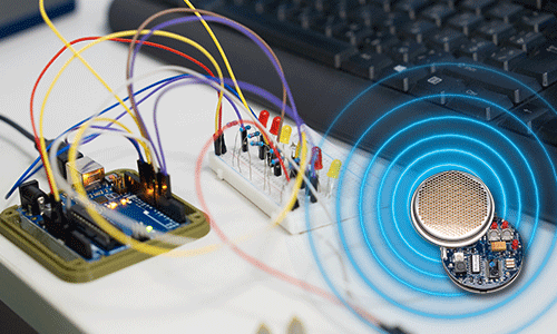
The kit contains a SensComp Instrument Grade Smart Sensor, a pre-programmed Arduino® UNO board, an I2C LCD display module, a 12 VDC 1 A power supply, a USB 2.0 cable, and ten male-to-female jumper wires. Out of the box, you wire the three boards together, plug in the supply, and the LCD shows live distance to a target in front of the sensor — no code required to see it working. When you’re ready to build your own behavior, the UNO runs the standard Arduino IDE; SensComp provides the Ping_SMRT.ino sketch (using the common Wire and LiquidCrystal_I2C libraries) as a starting point you can modify.
In practical terms, the sensor side gives you:
- A 600 Series electrostatic transducer — the same core transducer family behind SensComp’s industrial ultrasonic sensing platform.
- Integrated front-end electronics, so you provide a trigger and read an echo rather than designing a driver. The Smart Sensor takes a voltage-regulated 6–24 VDC input and returns a TTL-compatible PWM/ECHO output whose timing is proportional to target distance; the Arduino measures the elapsed time and converts it to range.
- A selectable update rate — clocked internally at 5 Hz, or externally triggered up to 50 Hz — plus onboard digitally controlled gain and a variable-bandwidth amplifier to manage noise and side-lobe detection.
The point isn’t the convenience of a quick demo. It’s that the convenience comes without stepping away from the sensing performance your production design may need.
How the SensComp Arduino Kit Bridges Prototype to Production
Four things make this kit a real prototype-toward-production path rather than a parallel detour.
You prototype on a production-relevant Smart Sensor platform. Because the kit is the Smart Sensor, the sensitivity, beam pattern, near-field behavior, and timing you characterize on the bench reflect what you’d get from that sensor in a product. Thresholds and logic tuned against real targets have a direct path forward. There’s no “hobby part to real part” cliff waiting late in the schedule.
The hardest electronics are already solved. The high-voltage transmit drive and the low-noise receive chain — the parts most likely to eat your timeline — are done and tested. Engineering time goes into the application: detection logic, data handling, user-facing behavior. For an R&D team, that’s the difference between debugging an analog front end and refining the thing you’re actually building.
You get real electrostatic performance from day one. Electrostatic transduction delivers roughly 40 dB greater sensitivity than a comparable piezo sensor, which is why it returns usable echoes from soft, absorptive, and irregular targets that commodity modules miss. Its low-ring (non-resonant) behavior shrinks the near-field blind zone that resonant piezo sensors suffer from. You’re validating against the strengths you’d actually use — not discovering them after a sensor swap. (Spec notes for your design: the Smart Sensor’s range window is 1.5 ft to 35 ft by default, with capability down to 0.5 ft depending on configuration; it transmits at a single ~49.4 kHz frequency in stock configuration; and the complete sensor is rated for 0 °C to +70 °C — narrower than the bare 600 Series transducer, so design the production envelope around the complete sensor. See the current Smart Sensor datasheet for full accuracy and operating specifications.)
There’s a defined path forward through related technology. SensComp’s lineup is built around three integration points that share the same electrostatic sensing foundation: the complete Smart Sensor you prototyped on; the 6500 Series Ranging Module, which provides similar drive, timing, echo processing, and a TTL output on a smaller board if you want to manage timing and output logic yourself; and the bare 600 Series transducer, where — at higher volumes or for tighter packaging — you design your own drive and receive electronics around the transducer. Moving down the stack toward a leaner BOM can be a continuation rather than a restart because the underlying sensing physics is consistent — but each integration point still has its own electronics and output architecture (the bare transducer especially), so each still needs application-level validation.
A Practical Path from Arduino Prototype to Production BOM
For an R&D program, the kit supports a clean progression:
- Validate the concept on the Arduino with the Smart Sensor against your real targets, in your real environment, and tune detection logic against representative data — starting from the included sketch and the live LCD readout.
- Characterize the envelope — usable range, beam coverage, target discrimination, and update rate (the Smart Sensor’s 5 Hz internal rate, or external triggering up to 50 Hz, helps you reason about how fast your application needs to sample). Calibrate the onboard gain for the minimum setting that gives reliable detection; excessive gain can increase false targets and side-lobe detection.
- Decide your integration point — stay with the Smart Sensor for fastest time-to-market, drop to the 6500 module for a smaller or lower-cost board, or move to the bare transducer with custom drive electronics at higher volumes.
- Move toward the production BOM carrying your tuned logic forward, with fewer unknowns because the sensing foundation is consistent across the path — while validating each new integration point in your own application.
Design Considerations for the Production Ultrasonic Sensor
A few practical notes save time later:
- Plan for the transmit current burst in your own design. The sensor draws up to 2.5 A peak for about 0.006 msec during transmit. On the bench, the included 12 VDC 1 A supply handles this (a high-power USB port may also work, but the wall adapter is recommended). Also, you should use a 47 uf tantalum capacitor minimum across the Vcc and ground circuit on your PCB design. This capacitor will supply the necessary charge to hold the supply voltage steady during the transmit cycle. Adding a 0.1 uf capacitor across Vcc and ground will help eliminate higher frequency power supply noise. A properly designed power supply with adequate current capability can supply all the circuits in your design, including a DSP or microcontroller.
- Mind the range window. Standard configuration measures from about 1.5 ft (0.5 ft capable), not right up against the sensor face; plan mounting and minimum-distance behavior around that near limit rather than assuming a zero blind zone.
- Single frequency is the default. The stock sensor transmits at one frequency. Multi-frequency techniques for external acoustical noise rejection are possible but require custom drive electronics and signal processing — design that in deliberately if your environment demands it, rather than assuming it’s built in.
- Match the grade to the deployment. The kit’s Smart Sensor is Instrument Grade, making it best suited for bench validation, protected environments, and development work. For outdoor or harsh production environments, specify the appropriate environmental-grade sensor (parylene coating, stainless housing) in the production design.
Start With an Ultrasonic Sensor You Can Carry into Production
The fastest prototype isn’t the one that gets a number on screen soonest — it’s the one whose results survive the trip toward production. SensComp’s Arduino kit lets an R&D team start on a production-relevant electrostatic sensor, skip the high-voltage circuit design that doesn’t differentiate their product, and follow a defined path from breadboard toward a BOM with fewer surprises in the sensing layer along the way.