

Every ultrasonic sensor output carries the same measurement, the round-trip time of an echo. What changes is where the timing happens, and that decides which controller input you need.
KEY ANSWERS AT A GLANCE
How does an ultrasonic sensor report distance? As the round-trip time of an echo. Distance equals the speed of sound multiplied by that time, divided by two. A transistor-transistor logic (TTL) echo output leaves the timing to the controller, a pulse-width output encodes it as the length of a pulse, and an analog output converts it to a voltage inside the sensor.
How do you read a TTL echo output? Time the interval from trigger to echo edge. On the 6500 Series Ranging Module, that’s the time from the INIT (initiate) input going high to ECHO going high, and ECHO is an open-collector output that includes a 4.7K pull-up resistor on all versions.
How do you convert a pulse width to distance? On the Mini-A, the pulse output goes high at the start of a cycle and low when the echo is detected, so the pulse width is the round-trip time. Each foot of target distance adds roughly 1.8 ms at 20°C.
When is an analog output the better choice? When the controller reads voltages more easily than it times edges, most often a programmable logic controller (PLC). The Mini-A outputs 0 to 5 VDC or 0 to 10 VDC between push-button MIN and MAX settings, and its analog output is temperature compensated.
Does the output type change what the sensor can detect? No. An output can only report an echo the receiver registered. Electrostatic ultrasonic transducers have approximately 40 dB greater receive sensitivity than piezoelectric ultrasonic transducers, which lets faint echoes from soft, low-reflectance targets register before any output encodes them.
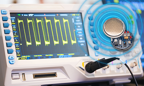
An ultrasonic sensor doesn’t measure distance directly. It measures how long an echo takes to come back, and the output stage decides how that time reaches your controller: as an edge to time, a pulse to measure, or a voltage to read.
Pair an output with the wrong controller and a working sensor produces bad data. A PLC input that updates every few milliseconds can’t time an echo edge, and a poorly set analog span spreads an input card’s resolution thin. Here’s how each output works and what the controller has to do with it.
How does an ultrasonic sensor report distance to a controller?
Every ultrasonic sensor output encodes the same measurement: the round-trip time between the transmit pulse and the returning echo. Distance equals the speed of sound multiplied by that time, divided by two, because the sound travels out and back. The output type only changes where the timing and conversion happen — in the controller for a TTL echo output, in a pulse width the controller measures, or inside the sensor for an analog voltage.
At 20°C, sound travels about 1,125 feet per second (roughly 343 meters per second). It covers about 0.9 ms per foot each way, so each foot of target distance adds roughly 1.8 ms of round-trip time. A target 10 feet away returns its echo in about 17.8 ms.
Temperature is the part that’s easy to miss. The speed of sound in air rises about 0.6 meters per second for every degree Celsius, so a 20°C swing shifts an uncompensated reading by roughly 3.5%, or about 4 inches at 10 feet. Wherever the time-to-distance math runs, temperature compensation has to run there too.
How do you read a TTL echo output from an ultrasonic sensor?
Time the interval between the trigger and the echo edge. On the 6500 Series Ranging Module, the controller takes the INIT input high to start a transmit, and the ECHO output goes from low to high when the returning echo is received. The time between those two edges is the round-trip time, which the controller converts to distance. The Smart Sensor shares the Ranging Module’s functions and outputs, so the same timing applies.
Four details decide whether that reading holds up:
- Use the on-board pull-up. ECHO is an open-collector NPN output, and every version of the 6500 Series Ranging Module includes a 4.7 kΩ pull-up resistor on the board, so the output is ready to connect to a controller input.
- Match the logic level. With the pull-up tied to VCC, ECHO swings to the module supply, nominally 5 V. A 3.3 V microcontroller needs a level shifter or a 5 V-tolerant input.
- Capture the edge, don’t poll for it. Every millisecond of timing error is almost 7 inches of distance error, so use an input-capture timer or a hardware interrupt rather than checking the pin in a loop.
- Set a timeout and a recycle interval. If no echo returns, ECHO never goes high, so the controller needs a timeout that reports “no target” instead of waiting indefinitely. The datasheet calls for at least 80 ms between cycles, with INIT returned low before the next transmit.
Budget for the supply, too. The Ranging Module draws up to 2 A for a very short time during the transmit burst and up to 100 mA afterward, so bulk capacitance near the module, or a separate rail, can help keep that pulse from disturbing a controller or other electronics sharing the same supply.
How do you convert a PWM pulse width into distance?
Measure how long the pulse stays high, then convert that time the same way as a TTL echo interval. On the Mini-A, the pulse-width modulation (PWM) output, labeled Clock Output on the datasheet, goes high at the start of each measurement cycle and returns low when the echo is detected. The pulse width is the round-trip time, so each foot of target distance adds roughly 1.8 ms at 20°C.
The advantage is that start and stop arrive on one wire. The controller doesn’t have to generate the trigger or track when the transmit happened. It measures a single pulse, which an Arduino’s pulseIn() function, a microcontroller input-capture timer, or a PLC high-speed input configured for pulse width can all handle.
The Mini-A measures continuously at 10 Hz, or it can be triggered externally at up to 50 Hz once its Trigger Enable pin is tied to common. Two cautions apply. The pulse is a 0 to 5 VDC logic signal, so it needs an input rated for that level. And because the conversion happens in the controller, the controller should apply the speed of sound at the current air temperature, just as it would for a TTL echo.
When is an analog voltage output the better choice?
Use analog when the controller reads voltages more easily than it times edges, most often through a PLC analog input card. The Mini-A outputs 0 to 5 VDC or 0 to 10 VDC, depending on the model, proportional to distance between MIN and MAX points set with push buttons against a real target. The sensor handles the timing and conversion internally, and its analog output is temperature compensated.
The MIN and MAX settings are where resolution is won or lost. An analog input divides its range into a fixed number of counts, so a 12-bit input card resolves about 0.09 inch per count across a 30-foot span, and about 0.006 inch per count across a 2-foot span. Set MIN and MAX to the distances the process actually uses rather than to the widest span available.
Reverse slope takes no extra wiring. Set the full-scale point at the near distance and the zero point at the far distance, and the voltage rises as a tank fills instead of falling. The 0 to 10 VDC models run from a 12 to 24 VDC supply, so a control panel’s 24 V rail can power the sensor directly.
The analog value updates at the measurement rate and is lightly filtered, so it isn’t the right fit for a fast-moving target. A voltage signal also picks up noise and ground offsets over long cable runs, so keep runs short and shielded, with the sensor common referenced to the input card’s common.
Which ultrasonic sensor output should you specify?
Match the output to what the controller does well. A TTL echo output suits a microcontroller that captures edges and needs control over trigger timing, a pulse-width output suits single-wire timing, and an analog voltage suits a PLC or a measurement that doesn’t follow fast motion. For simple full and empty control, switchpoint outputs skip the distance value entirely.
|
Output |
What reaches the controller |
Where distance is calculated |
Typical controller input |
SensComp example |
|---|---|---|---|---|
|
TTl echo edge |
ECHO goes high when the echo is received, after INIT goes high |
Controller |
Input capture or interrupt, 5 V logic |
6500 Series Ranging Module, Smart Sensor |
|
Pulse width |
A pulse held high from cycle start until the echo is detected |
Controller |
pulseIn(), input capture, or a PLC high-speed input rated for 5 V |
Mini-A Clock Output |
|
Analog voltage |
0 to 5 VDC or 0 to 10 VDC between MIN and MAX |
Sensor, temperature compensated |
PLC or analog-to-digital converter (ADC) input |
Mini-A Analog Output |
|
In-window logic |
Logic 0 while the target sits between MIN and MAX |
Sensor |
5 V logic input |
Mini-A Range Output |
|
Switchpoints |
Two switch outputs, typically set for full and empty |
Sensor |
Discrete input |
Mini-S |
Every one of these outputs shares a limit: it can only report an echo the receiver registered. That applies to ultrasonic sensing broadly, and receive sensitivity decides what reaches the output in the first place. Electrostatic ultrasonic transducers have approximately 40 dB greater receive sensitivity than piezoelectric ultrasonic transducers, so the faint return from a soft, low-reflectance target such as fabric, foliage, or a person can still register as a valid echo instead of a timeout.
Frequently Asked Questions
Multiply the round-trip echo time by the speed of sound and divide by two. At 20°C sound travels about 1,125 feet per second, so each foot of target distance adds roughly 1.8 ms of round-trip time, and a 17.8 ms echo corresponds to about 10 feet. The speed of sound changes with air temperature, so apply compensation wherever the calculation runs. The analog output on the Mini-A and switchpoint outputs on the Mini-S are temperature compensated inside the sensor.
Yes, most directly through an analog voltage input. The Mini-A, an electrostatic ultrasonic sensor, outputs 0 to 5 VDC or 0 to 10 VDC proportional to distance between push-button MIN and MAX settings, and the 0 to 10 VDC models run from a 12 to 24 VDC supply. Timed outputs are harder for a PLC, because a standard discrete input often updates too slowly to time an echo and every millisecond of error is almost 7 inches of distance. A TTL echo or pulse-width output needs a high-speed input rated for 5 V logic. The Mini-S has two (2) switchpoint outputs.
Yes. With the 6500 Series Ranging Module, which drives electrostatic ultrasonic transducers, the Arduino takes INIT high and times the rising edge on ECHO, ideally with an interrupt or input capture rather than polling. The output swings to about 5 V and a 3.3 V board needs a level shifter. The Mini-A pulse-width output can be read with pulseIn() instead.
No. The 6500 Series Ranging Module, which drives electrostatic ultrasonic transducers, has an open-collector, TTL-compatible ECHO output that goes high when the echo is received, and the controller converts the elapsed time to distance. Where an analog output is needed, the Mini-A has a 0 to 5 VDC or 0 to 10 VDC output proportional to distance, along with a pulse-width output and an in-window range output.